

Usable Coverage. Commercial restroom sensing
ArchFaucets · Commercial restroom engineering
Sensor Range vs Detection Zone: What Matters in Commercial Restrooms?
Sensor range tells you how far a faucet may detect a target. The detection zone tells you where hands can actually activate it. A successful commercial installation needs usable coverage over the basin, predictable timing and rejection of unintended movement—not simply the longest advertised range.
For architects, plumbing engineers and facility teams, the distinction affects spout placement, basin selection, accessible use, adjacent soap dispensers and commissioning. Two faucets with similar distance settings can behave differently once installed. Their sensor orientation, optics, controller logic and surrounding surfaces may differ.
Technical scope: lavatory sensor faucets and adjacent dispensing systems. Diagrams are conceptual; calculated examples are not laboratory measurements, product rankings or universal acceptance limits.
Range is one dimension. Usable detection is spatial.
What a range setting does—and does not—tell you
A listed range may describe a factory setting, an adjustable interval or a measurement made with a specified target. It does not automatically describe the width or height of the working field at that distance.
Ask where the measurement starts: the optical window, the sensor module or another documented datum. Record the direction of measurement. A diagonal sensor-to-hand distance is not the same as vertical clearance beneath the spout.
Submittal question
“Identify the range reference point, adjustment method, target conditions and available field-of-view information. Confirm which settings are accessible to the installer.”
Map the working region around the hands
For this article, the operational detection zone means the positions where a defined hand approach produces the intended response under stated conditions. It includes lateral position, height and approach direction, not only distance.
Keep optical field of view, valid sensor measurements and controller activation separate. STMicroelectronics’ AN5894 field-of-view note distinguishes nominal optical fields from valid ToF detection volume, which changes with target and environmental conditions.
Why a cone sketch is only a starting point
A drawing helps coordinate geometry. It cannot establish successful detection at every point. Confirm the assembled faucet with real approaches and the final basin surfaces.
| Term | Engineering meaning | Required clarification |
|---|---|---|
| Range | Distance setting or stated detection reach. | Datum, target, conditions and adjustment limits. |
| Field of view | Angular optical coverage described by the sensor supplier. | Horizontal, vertical or diagonal angle; full angle or half-angle. |
| Activation zone | Installed region in which the configured faucet responds to the test approach. | Map at several heights and lateral positions. |
| Activation latency | Elapsed time from the defined entry event to observed water delivery. | Measurement start and finish; distinguish controller and hydraulic delay. |
| Shutoff delay | Time between target departure and cessation of flow. | Separate from maximum-run timeout and metered operation. |
Coordinate the optical path with the washbasin
The following are proposed project checks. Use them with the exact manufacturer’s instructions, rather than treating them as a universal calibration procedure.

Align sensing with the usable washing area
Coordinate the sensor axis, outlet position, basin rim and the place where hands naturally meet the water. A setting that detects hands near the front rim may still miss them under the stream.
Record sensor-to-basin relationships in both plan and section. Include the nearest basin wall, drain fitting and countertop edge. Changing spout reach or mounting height can change the surfaces visible to the sensor.
Check on the mock-up
Approach from the front and both sides, then repeat at lower and higher hand positions within the intended washing area. Record the positions requiring a second attempt.

Test reflected targets and changing daylight
Include glossy ceramics, polished metal, mirrors, water droplets and the final lighting arrangement in the evaluation. Inspect whether the faucet starts before hands reach the basin or responds to activity outside the intended station.
GROHE’s detection-area training discusses adjusting supported infrared taps when early activation or reflective clothing causes unwanted flow. That guidance is specific to the supported product and control system.
Document the lighting condition
Record daylight exposure and fixture positions. A room illuminance reading alone does not characterize the infrared energy reaching an optical receiver.

Separate faucet and dispenser activation paths
A hand moving toward soap may pass through a faucet’s active region. This is a geometry and sequencing problem even when the two devices do not optically interfere with each other.
Operate each station separately, then simultaneously. Include hands crossing between fixtures and pass-by movement. Record what each sensor can physically see before attributing a false activation to electronic or optical crosstalk.
FontanaShowers’ faucet and dispenser detection-zone resource distinguishes the two activation regions. Confirm that its dimensions apply to the selected assembly.

Observe a complete washing sequence
A single successful trigger is not enough. Observe entry, normal hand movement, brief departure and return, rinsing and final withdrawal. Note unwanted interruptions as well as unintended continued flow.
Include users with different reach and hand positions, and the intended accessible approach. Test relevant gloves where the project requires them. Do not compensate for a difficult reach merely by increasing distance.
Separate user experience from sensor output
A sensor may recognize a target before water reaches the hands. The valve, supply and outlet also affect perceived response. Record the whole event rather than calling every delay a sensor fault.
Separate sensing technology from control behavior
Ask what the installed system measures
“Infrared” describes a spectral region; it is not the opposite of time-of-flight. Optical ToF sensors can also use infrared light. Ask whether the selected faucet uses reflected-signal proximity, distance measurement or another documented sensing method.
Some ToF modules support a configurable region of interest, but that does not mean a faucet exposes this adjustment to an installer. ST’s VL53L1X documentation provides a component-level example of ROI control, not a specification for any faucet shown here.
Target reflectance, ambient light and timing settings can influence valid ToF measurements. Do not assume a ToF label guarantees immunity to difficult optical conditions.
Record four different events
- Target entry: the defined approach crosses the test boundary.
- Water delivery: flow begins at the outlet or reaches the target point—state which.
- Target departure: hands leave the active region.
- Flow cessation: water delivery ends.
Maximum-run timeout limits a continuous activation; it is not the normal shutoff delay. Metered operation may intentionally run for a programmed period. Automatic hygiene flushing is another separate function.
Moen’s INS10474B instructions distinguish detection-distance programming from metering and Sentinel Flow settings. Check the applicable model and revision before adjusting.
Manufacturer references: Brands for commercial options
These references demonstrate why a single “standard sensor range” is unsuitable for every commercial faucet. They are documentation examples, not a brand ranking or confirmation that every current model shares the same controls.

Range and timing are separate adjustments
Delta’s DEMD-301/311 instructions identify an adjustable sensor range and describe an optional remote-control adjustment process. The document also treats security time separately. Confirm the installed model before applying its procedure.
Review Delta Instructions →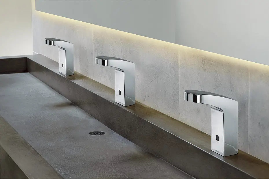
Record the operating mode with the distance
Moen’s INS10474B manual includes detection-distance, metering and Sentinel Flow programming. A distance setting alone is incomplete handover information when the controller’s operating mode changes how water continues or stops.
Inspect Moen Programming →
Keep the sensing area clear during setup
TOTO’s ECOPOWER installation manual describes automatic sensing-range adjustment after the sensor connection is made and instructs installers to keep hands and objects out of the sensing area during that process. Follow the exact startup sequence for the selected model.
Check TOTO Startup →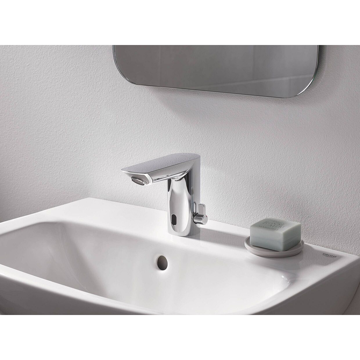
Fine-tune supported detection settings
GROHE’s Bau Cosmopolitan E training describes remote adjustment through detection levels. It also identifies reflective clothing as a possible unwanted trigger. Treat adjustment as a response to observed behavior, not a reason to maximize reach.
Explore GROHE Detection →
Coordinate water and soap activation
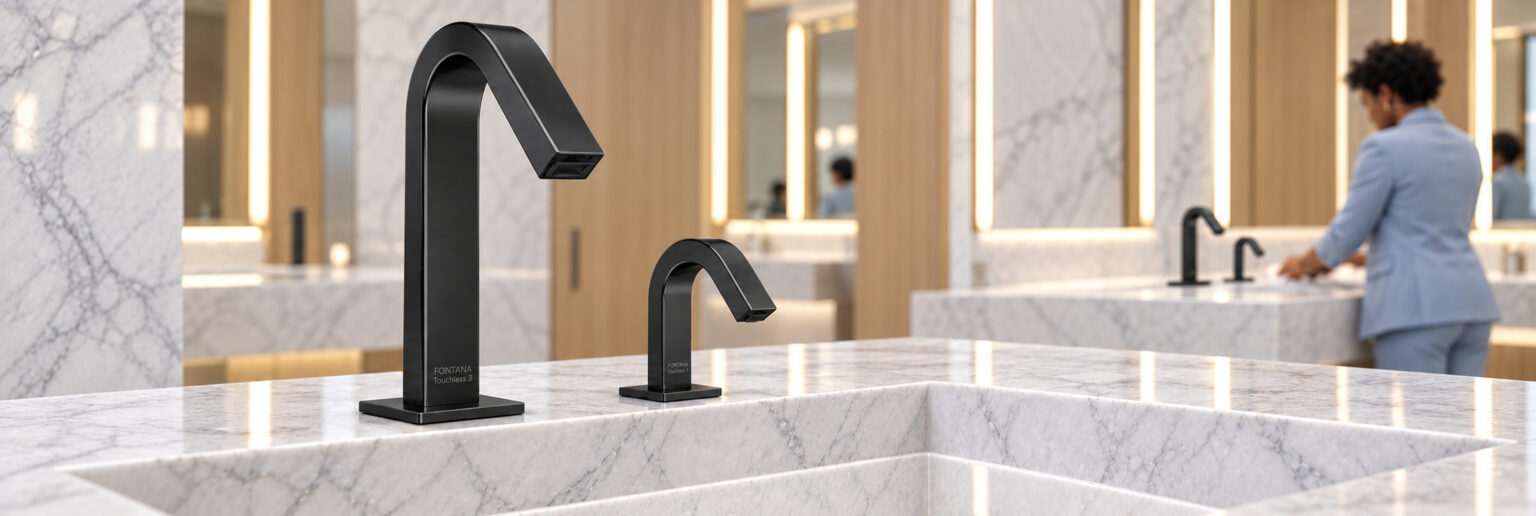
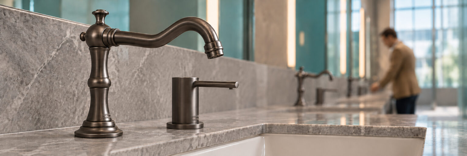
The pictured Fontana Romo set provides a practical reference for reviewing two touchless functions at one washbasin. Evaluate the approach to each outlet and whether reaching for soap unintentionally starts the water.
FontanaShowers’ detection-zone resource addresses sensor orientation and separate faucet and dispenser operating regions. Obtain the pictured model’s own installation documents before adopting any dimensions or settings from a general coordination drawing.
Study Fontana Coordination →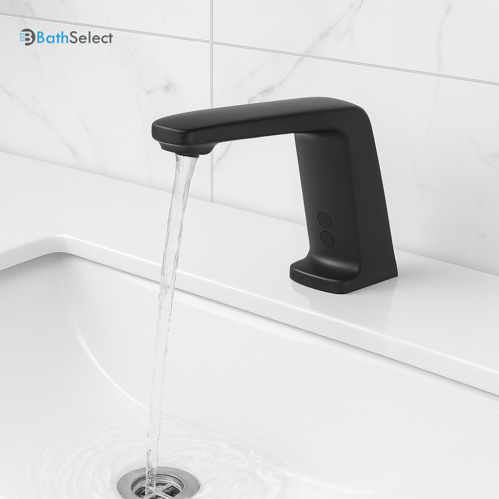
Review the installed hand-approach area
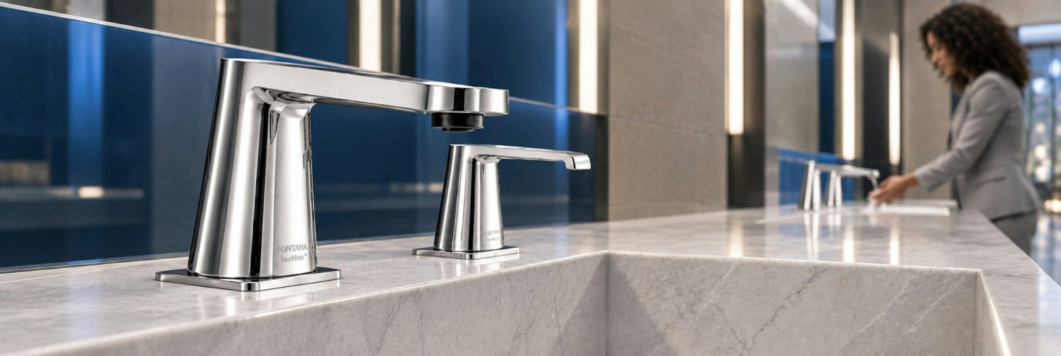
The pictured BathSelect Chicago faucet is a deck-mounted sensor configuration. Review the sensor position, outlet reach and basin relationship together, then confirm the selected model’s calibration and operating instructions.
BathSelect’s separate BST515R reference illustrates why published distance descriptions require context: its page includes differing sensing figures. Obtain a confirmed model-specific submittal rather than treating one listed distance as the complete activation zone.
Explore BathSelect Fixture →Review Detection Reference →
Commission the detection zone, not just the centerline

A repeatable field procedure
- Record model, controller, power source, basin, outlet and settings.
- Complete manufacturer startup with the sensing area in the required condition.
- Define the intended washing region and repeat approaches at its center and edges.
- Repeat with final lighting, representative users and relevant operating conditions.
- Operate neighboring faucets and dispensers separately and together.
- Measure start, interruption and shutoff behavior using consistent definitions.
- Record corrections, then repeat the same checks after adjustments.

Publish the denominator behind every score
First-attempt success: record successful initial activations alongside the total number of valid approaches. Define the allowed response interval before testing.
Unintended activation rate: unwanted flow events per observed idle fixture-hour. Keep planned automatic flushes in a separate category.
Interruption rate: record trials with an unintended cutoff alongside the total number of valid washing trials. Record whether a programmed timeout or metered mode explains the event.
Restoration check: after sensor, optical-window or controller replacement, follow the manufacturer’s setup process and repeat the original acceptance checks.
| Condition | Observation | Evidence to retain |
|---|---|---|
| Center and edge approaches | Missed starts, extra hand movements and response time. | Marked positions, approach direction and attempts. |
| Daylight and final luminaires | Changed boundaries or spontaneous activation. | Time, lighting state and nearby reflective surfaces. |
| Soap-to-water transition | Faucet triggering while reaching for soap. | Hand path and fixture spacing. |
| Neighboring stations | Activation caused by adjacent users or crossing hands. | Which devices operated, sight lines and event sequence. |
| Cleaning and return to service | Contamination effects, settings retained and normal operation restored. | Approved cleaning method and post-cleaning result. |
| Power restoration | Startup, calibration and settings retention. | Manufacturer procedure, settings and repeat checks. |
Graphs that explain geometry and water-on time
The same distance can produce different field widths
This graph compares two ideal sensing-cone angles at four distances. A wider angle produces a wider cross-section at the same distance.
Distances are measured along the sensor axis. Angles describe the full opening in the evaluated plane; horizontal and diagonal angle specifications are not interchangeable.
At 200 mm, the calculated widths are 70.5 mm and 145.6 mm. These are ideal geometric sections, not guaranteed detection boundaries. Real sensor fields and accepted targets may differ.
Additional run-on accumulates with use
Assume 1,000 uses each day at a constant 0.5 US gpm. The bars show additional daily water associated only with the stated post-departure flow duration.
A shorter delay is not automatically the right setting if it interrupts intended use. Evaluate stable operation and actual consumption together. These values are neither recommended handwashing durations nor measured performance of a named faucet.
Separate intended flow from other events
Example day: 1,000 uses, each with 12 seconds of intended flow and 2 seconds of run-on, plus 100 unintended events lasting 4 seconds each. Assume 0.5 US gpm throughout and no scheduled flushes.
This constructed example explains the accounting method. It is not a typical restroom breakdown or a recommendation for washing time.
The daily-use example in plain numbers
| Event | Water-on time | Gallons |
|---|---|---|
| Intended | 12 seconds per use | 100.00 |
| Run-on | 2 seconds per use | 16.67 |
| Unintended | 4 seconds per event | 3.33 |
| Total | 14,400 s | 120.00 |
For a real audit, record actual event durations and flow. Identify automatic flushes separately. If flow changes during use, integrate measured flow over time instead of assuming one constant rate.
Government guidance: sensing is one part of the installation
A reachable zone does not replace accessible geometry
The U.S. Access Board’s lavatory guide addresses clear approach, knee and toe space, height, controls and protected exposed plumbing. Coordinate these requirements with the installed basin and faucet rather than assuming that touchless operation alone makes the assembly compliant.
The minimum 10-second requirement for hand-operated metering faucets should not be applied as a universal motion-sensor setting.
Read Access Board Guidance →Match efficiency claims to the faucet category
EPA distinguishes public lavatory faucets from private lavatory and bar sink faucets covered by WaterSense labeling criteria. It identifies 0.5 gpm or less for efficient public lavatory use; verify locally applicable requirements and the actual fixture classification.
A sensor range adjustment is not a WaterSense certification, and a flow rating alone does not establish total water saved.
Review EPA Faucet Guidance →Coordinate splash and water-management risks
CDC advises healthcare teams to manage water-system risks and reduce exposure from sinks and drains. Its guidance includes sink design choices that reduce splash. Successful sensor activation does not establish infection-control effectiveness.
Review outlet alignment and the washing area with the responsible infection-prevention team where applicable.
Consult CDC Water Guidance →Specify an outcome that can be checked
“Submit the sensor operating principle, documented range settings, available field-of-view information, calibration procedure, operating modes and service instructions for the proposed model.”
“Demonstrate intended activation across the agreed washing area and test neighboring fixtures, final lighting and relevant user approaches. Record settings, failures, corrective actions and repeat-test results at handover.”
Project specification example, not a code clause. The design team must establish acceptance criteria and applicable requirements.
Sensor range and detection zone: technical FAQs
Does a longer range make a commercial sensor faucet better?
No. The useful setting is the one that supports intended hand positions without responding unnecessarily to the basin, passers-by or adjacent fixtures. Evaluate the final assembly and operating mode.
Can two faucets set to the same distance have different detection zones?
Yes. Sensor orientation, optical coverage, target conditions and controller logic can differ. A matching distance value does not establish matching lateral or vertical coverage.
Is time-of-flight sensing independent of lighting and surfaces?
No. ToF measures distance, but valid measurements still depend on the sensor’s optical operating conditions. Confirm the assembled faucet’s documented limits and field behavior.
Should the detection zone be adjusted before or after installation?
Follow the manufacturer’s installation sequence. Final acceptance should use the installed basin, finished surfaces and final lighting. Automatic calibration may require keeping the sensing area clear during a defined startup period.
What information belongs in the handover record?
Keep model and controller identification, installed geometry, settings, power arrangement, manufacturer instructions, test positions, observed results and service-part references. Record later changes and repeat the relevant checks.
